Portfolio

Showing posts with label MIT. Show all posts

Monday, December 31, 2012

I'm a Beardy-Weirdy?

S'up guys,

This was my year of being old and cranky (senior fall), so I decided to become a beardy-weirdy (analog-esque EE). For some reason, I always associated analog people with old engineers probably because I once saw a picture of Bob Pease and assumed all analog-ers looked like this.

"My favorite programming language is ... solder"  
Unfortunately, this gave me the impression that if I were to become an analog EE, all the people in my life would be sarcastic, scraggy Santa Clauses...(someone is going to kill me for this comment so here's my pre-emptive apology). While I'm sure Bob Pease was a creative man and had a dry sense of humor, you could imagine how this could put off a naive, girly-as-hell EE. In no way am I saying Bob Pease wasn't freaking baller nor am I saying there are no female and/or young analogs. Just not many...

(Btws, this was before I realized that Prof Roberge used to look like James Bond back in the day, so clearly there was evidence of well-dressed analog people)

Regardless, I decided to brave the challenge, so I signed myself up for MIT's 6.301 (Solid State Circuits). Glad I did, because that class was awesome!

First off, my main gripe with MIT undergraduate classes is that they aren't very "design-y". 6.301 is a grad class, but I wish more of my undergrad had been like it. For the most part, I felt like I was always learning fancier and fancier math, but never how to create with it. , In my opinion, a lot of the 6-1 (EE) curriculum consists of churning math out. It's basically the opposite of creative. You learn a protocol, you apply that protocol to constrained examples in homework and tests, then you're done. What I hate about this is that you're not given an opportunity to be particularly creative. You don't jump and apply concepts from one field to another (well I sort of did in 6.021 (BioEE) - fun class), but for the most part, you don't really even apply it outside of that week's lecture. This is why I've built things outside of class, because I couldn't stand this system. I've always thought the best way to prove myself that I've learned something is to use it. I'm afraid most undergraduates aren't taught to be innovative. That scares me! We might graduate more and more engineers, but we'll only make limited progress if we can't be creative. People must to learn to imagine what does not yet exist...although I admit it's a daunting task.

6.301 is quite different! Instead, you learn a bunch of design ideas for why certain topologies are good/bad, what are trade-offs between them, etc. Sometimes we would go through a specific design in a series of lectures and see how a designer might conclude with that circuit through various estimations/intuition. There are also these excellent course notes by Kent Lundberg which are super awesome. During the course, you get to run wild and design three circuits from scratch.

Anyway, long rant short, I wanted to summarize the things I designed for 6.301. I really loved this class :D


Lab 1:

Oh man, my first circuit with BJTs that didn't catch on fire! Previously, anything I ever built with BJTs somehow, at least once, caught on fire. Don't ask why. Too embarrassing :X I did always fix them though. This is also my least elegant circuit probably because it was my first. Everyone's gotta start out somewhere...
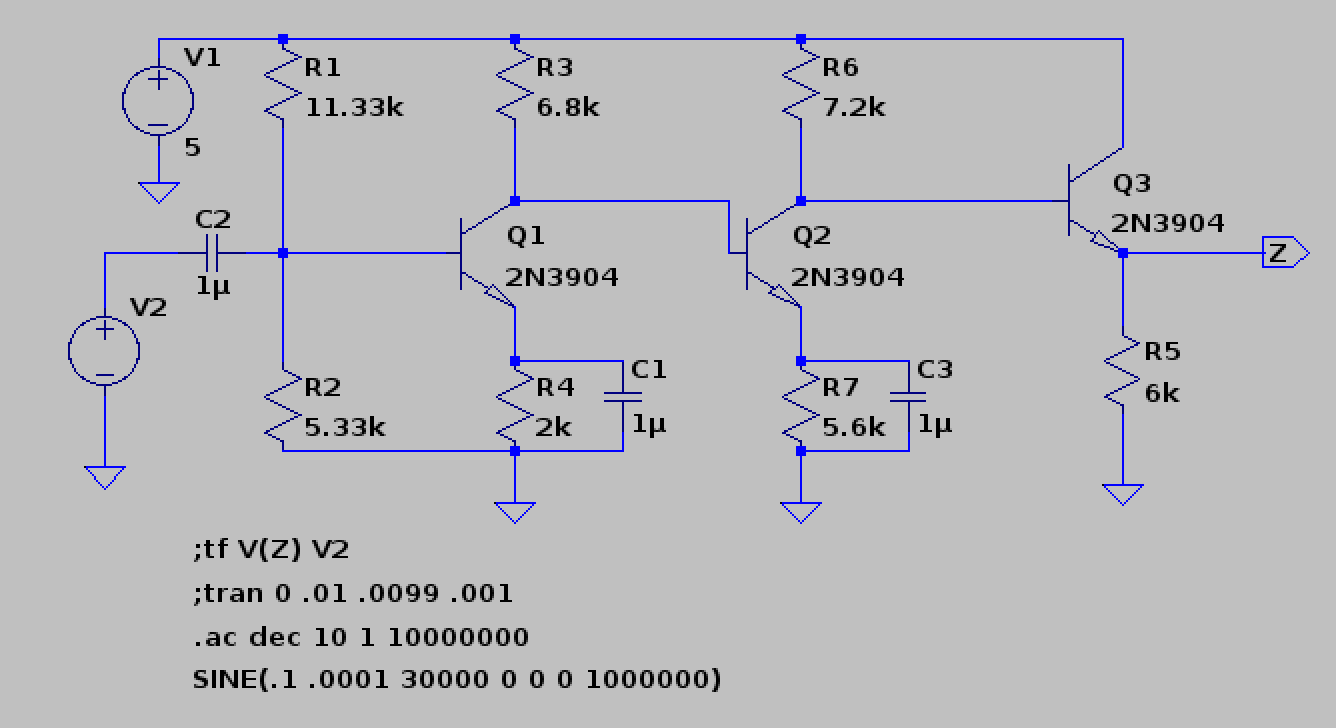
I'm derpy.

The goal of this lab was to make a 3-stage amplifier that met these specs:

We were learning about common-emitter amplifiers, and so the smart thing to do was put caps on the emitters to make the AC voltage gains super high. It's still nice to have emitter resistors to set Ic, and, more subtlety, set a DC gain. At DC, your caps should theoretically be open, so then you have common-emitters with degeneration. So, if your resistor divider sucked or some weird stuff, your DC voltage would be amplified by much less than your AC. Yay! This knowledge really isn't terribly useful in this circuit because your DC is pretty set by that voltage divider and nothing in this 3-stage should be seriously gross because you only go to ~150 kHz. 

I made my circuit and it met spec in spice, and I was super happy until this really weird thing happened. 


You'll notice in the spice sim that the upper 3dB point is about ~165 kHz. Er, somehow when I made it on my breadboard, my upper 3dB was at 1.2 MHz.

Confusing to say the least.

Another kid had this problem too and the TAs said this did happen although they didn't figure out why. That kid was also a total jerk! He condescendingly asked me why I was even in 6.301 "to make clothes out of transistors?"

...

Just because a female EE dresses well doesn't mean that's all she does. Man, that almost made me fear all hopeful analogs were morons...

Anyway, back to the point, what actually occurred was that my circuit was resonating. One way to check is by sending a DC signal through your amplifier and seeing if you get some oscillation on the output. My resonating problem was due to this attenuator which we had to build for our signal generators because they couldn't put out a low enough voltage. 


Note: we have the 50 Ohms to make a nice, nonreflecting transmission line when your signal generator is set to 50 Ohm output. However, we weren't going fast enough in this lab for it to really matter. Nice info to know though (for say, an internship maybe). 

I had accidentally set the 1k going to my circuit (the rightmost one) as 10k. This didn't change my overall gain, but it did make my circuit resonate just enough to make my upper dB look like it was 1.2 MHz. Wonky stuff. 


Lab 2:

This was definitely a more challenging one. We had to make a wide-band amplifier that met these specs:


Because I wanted to be hardcore, I wanted to use less than 6 transistors and use less power. My final product ended up with 5 NPNs (originally designed for 4 NPNs but I ran out of time to bootstrap out the breadboard capacitances).

I wanted to cry because my first version had 4 NPNs :( My final (this one) had 5. 
To begin, because of the 3 MHz, I knew it had to be fast. So what are fast? Well cascodes! Hence, I knew I needed at least 2 cascodes to get that gain (you can, I think, do it in one but you consume more power. You could also do a super decked-out tall cascode). Emitter-followers are also fast, so I kept that as backup. 

The first thing I thought of when I encountered this lab was the obvious. Now, you've probably just read my thoughts on "churning out engineering", so I didn't want to do the cookie-cutter method. The most obvious design to me was a +15 to -15 rail with 6 BJTs divided like my above circuit except with an additional emitter-follower. You could put this extra emitter-follower on the output so you never have to worry about your scope capacitance and output resistance being a low-pass filter on your overall signal. You could also put this extra emitter-follower at the beginning before your first cascode to reduce that open time constant. However this, to me, seemed power-hungry and since we only needed 1V peak to peak, I knew you could run this whole thing on 5V to GND. Also I didn't think it needed that many transistors because I thought without some emitter followers, you might still be fast enough. Here was my thought process:  
  • +/-15V rails means 6x the power of one 5V to GND. We need 1 Vpp, can probably use 5V.
  • Emitter-Follower at the beginning probably not needed because cascode is fast enough on its own. 
  • Might not need emitter-follower buffer in the middle either unless the second cascode's input resistance drags the whole thing down. 
  • Emitter-Follower at the end of the second cascode might not be needed if I keep in mind our upper 3 dB is at 3 MHz. Need to make sure time constant of 10pF * output resistance cuts it for 3 MHz (hence, my max output resistance must be < 5k).
  • Since I don't know how to do feedback circuits yet, why not do the whole different DC gain from AC gain so I don't have weird stuff. Let's put caps across some of my resistors in my cascode to set a higher AC gain than DC. Note: these caps should always go to ground because switching power-supplies are noisy...
With these things in mind, I drafted up my first lab 2,

I'm so baller because I have 4 transistors! 

Boy does that just graze 3 MHz...

Er, my first draft met spec...in sim...barely. So, with a doubtful heart, I made it on a breadboard. Its bandwidth (without bootstrapping) never went more than 2.2 MHz which was sad since it was designed for a little over 3 MHz...

Now normally, I probably would've brought out the big guns and bootstrapped that circuit to death, but this was hell week at MIT, so the physical circuit was due in less than 6 hours...er yeah....

I then went back and thought of the emitter-followers I removed. I realized that because I was hitting the limit of my gain-bandwidth product, I had to separate my gains of my cascodes more (because the second cascode loaded down the first). So, I threw a quick emitter-follower in the middle and used it as a voltage buffer and voila. Yay magic!
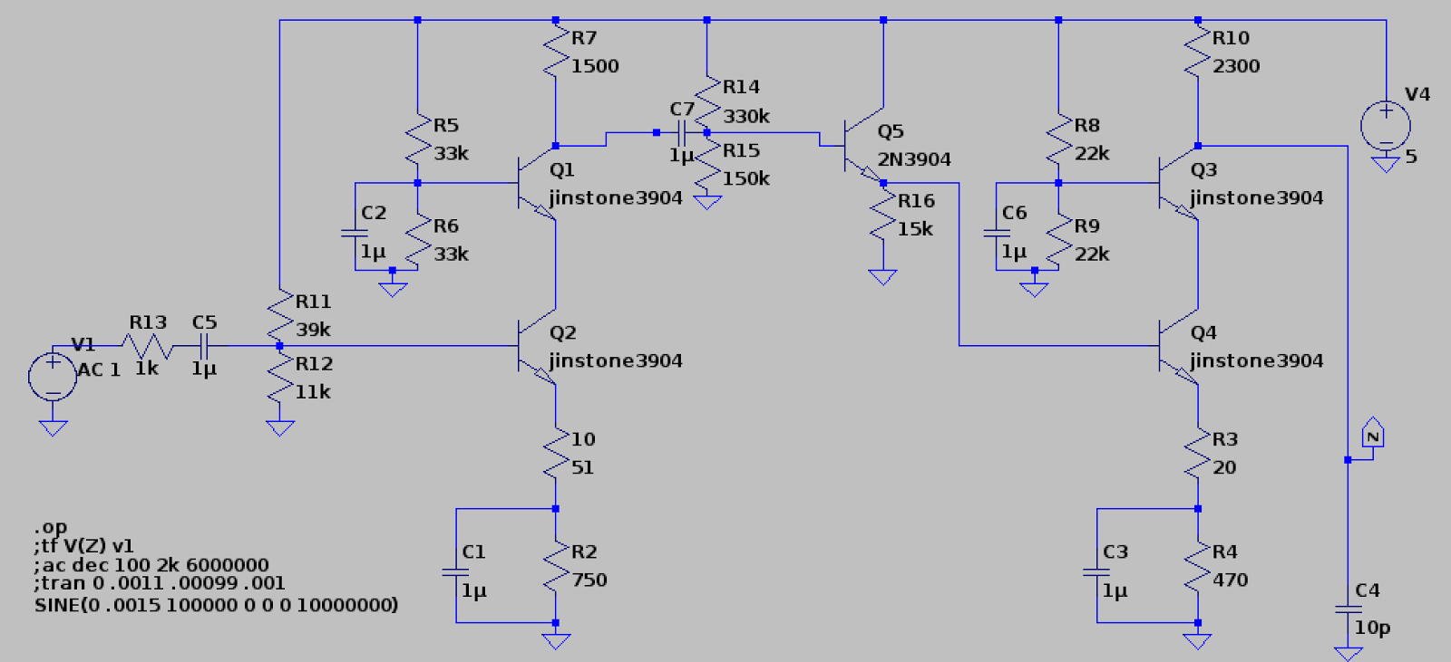
Again, my final design from before.
That magical feeling of meeting spec because your sim spec is way bigger!
P.S. it also took 5mW power. SO PROUD :D

Lab 3/Final Design Project:

For our final project we had to design a transimpedance amplifier (which is NOT an op amp). The cool thing about transimpedance amps is that their gain and bandwidth are decoupled! You can set them individually, which you can't in an op amp! Also they have no slew rate limit because you supply your own current input! Hence, they are super hella-fast. However, because they're low-impedance input & high-impedance output, you can't do nice things like integrators, differentiators, etc. 

You can't have everything in life. Boo. 

For the circuit, we were pretty much given an outline beforehand. 


Specs were:


Now the main deal about the design project was that you could either build it or write a project. I was obviously going to go for build (hence a nice thing about this post is that I remember what I did) :P

The whole diamond circuit buffer input we were given, so we couldn't change that, and we were told to bias it at 1mA. The main things we could pick were the mirrors and our output buffer. 

There were a few subtle things about this amplifier. First off, normal current mirrors don't have a high enough output impedance to provide a 200k node at DC. You have to use something else, so I picked Wilson mirrors. There were weird things about them though... 

Final Transimpedance Amp

First off, if you used a modified Wilson on the bottom NPN current mirror, it brought the open loop DC output bias from 13V to 3V. I think this had to do with transistor matching because the PNPs and NPNs were pretty unbalanced in not only the 301 models, but also ltspice's default ones (I sim'ed them in both because I got confused over some of these irregularities). A better way to get rid of these mirror discrepancies is to use emitter degeneration (which I didn't) to match them better (because closed loop testing hides your sins). 

Also, the output resistances of the Wilson mirrors were beta*R_out. Normally, these should be (beta*R_out)/2. I still am not quite sure why that occurred. I'm guessing that because they attach onto the original diamond, the left branches of the mirrors are technically stacks of 2 or 3 transistors, so the overall output of the mirrors are beta*R_out. This is just my intuitive guess though... 

Another thing I did was make the output buffer not a kosher diamond circuit. The obvious thing (since you were already given a diamond to begin with) is to stick another diamond at the end since it is a +1 buffer. However, the output buffer circuit I used consumes less power, forces Q9 and Q10 to never saturate, and bootstraps those transistors as well. A word of caution though - you can't use the output buffer as a replacement for the input diamond circuit. This is because the input and output are tied together (hence you get some bootstrapping and V_ce = ~.6V). When you use a buffer as the input for your transimpedance amp, you take the normal "output" and the normal "input" and use them both as inputs so you can get at least one low-impedance node. 


Now, the problem is that because your "input" and "output" are tied in the last stage's buffer, I feel that you're going to get weird, coupled problems if you use that buffer topology as an input. It's perfectly fine as an output though, because you leave its "output" alone. When you couple them together, you might get a weird V_be offset from +Input to -Input as well. Since this would be placed in the very inputs of your overall amplifier, even in closed loop, that offset would be amplified through the whole system and show up on your output. Gross :( 

Also, one last thing about the transimpedance amp is that I could've used better current sources. Every .6V you put across one V_be leg for a mirror, the other leg outputs 10x as much current. Hence you can save power by having one leg be 0.1mA and the other be 1mA. I did this with resistors, but you could do it another way. You also don't need 1mA to bias your buffers (you can cheat power with less and it'll still be fine). 

Here's my super cute hipstergram of my transimpedance amp :P

Analog Hipster

I deadbugged the main "compensation"-esque capacitor from the mirrors to the output buffer to maximize my bandwidth. I also used fingernail polish to paint my PNPs (pink) and NPNs (blue) so I wouldn't go insane! I even put the numbers of my transistors from my spice model so I could easily debug if needed, but luckily enough, it worked the first time :D YAAAAAAAAAAAAAAY

MAGIC

Phew! 

Well, that document's this year's transition into beardy-weirdiness. I feel like this is sort of an abrupt ending, but oh well. Hopefully I'll have another long rant to give you all next semester. 

Toddles,
Jordan


Monday, November 5, 2012

The Complementary Filter for Dummies

For 6.UAT (Undergrad Presentation Class), I had to give a talk to high schoolers about some technical subject. Since BabyCopter and Segboard both need to measure angle, I talked about the complementary filter. Here is my lolzy presentation. I tried to put it on youtube to preserve my multiple animations (a picture's worth a thousand words, an animation's worth ten thousand). If it's too fast, spacebar is your best friend.


Franken-BabyCopter

First off, Babycopter's alive again somehow. Although it might be about 20-30% hot glue... I'm not quite good at flying yet. I'm no Ryan Archer (so Shane is flying it).


Basically there is this super baller guy named kapteinkuk (translate his name from Norwegian haha), who wrote a flight controller in atmel assembly because C was too annoying for him. Kinda lolzy but true story bro. He's completely awesome and created the KK flight controller series which can be purchased from hobbyking. I suggest looking at the KK2 board which has all the assembly code under the "files" tab. 

I also will make Y6 before I die because I keep putting it off. However, I want another quad that isn't structurally made of hot glue first, so I bought the another frame from hobbyking. So yeah, prolly will have a TalonBaby before Y6.

Also, name suggestions for Y6? I'd like something with the baby motif...


Monday, June 4, 2012

NEVER Build a Quadrotor for 6.115

Don't ever program a quadrotor in assembly, or for that matter try to build one with an 8051 core unless are: 1) a wizard or 2) have a chip which runs a couple of MIPS, has loads of memory, more than one UART/SPI/I2C, an onboard boot loader, and isn't larger than your quadrotor. Even then, you still might hate yourself.

(P. S. It's a bad sign if your processor is older than you...)

Also don't buy a (surprise! ratiometric) analog IMU because you wanted to skip I2C, JUST LEARN I2C.

Me on the outside
Me on the inside.
Unfortunately, for my Microcontroller Class (6.115), I stupidly (well, rather naively), decided that making a quadrotor for a final project would be cool. And then I stupidly decided to change Babycopter (my originally "analog-esque" quadrotor) to digital because I'm an idiot (to be fair, it would've been hard in analog too).

*sigh* Sometimes I make such HORRIBLE decisions.

So my lovely, adorable, sweet quadrotor turned into a SOFTWARE NIGHTMARE, but before we get to that part, let's start out with what I like best - hardware.

Analog PD controller:
Gross but at least easy to tweak.
True, doing all the analog controls ever wasn't going to be pretty but hey, they make quad op amp packages. Also yeah, those high-passes freaked the crap out of me, but I kinda prayed and hoped and then ran into a piece of knowledge that basically made me switch to digital.

The AT89C2051 hasn't a DAC or an ADC and to implement them would require a lot of (unavailable) space. What kind of freaking chip doesn't have a DAC or ADC onboard?

Oh yeah, one that's 5 billion years old.

For those of you who don't know, 6.115's final project requirements are that you have to have some assembly-written program on some 8051 core, of which you have available either a real 8051, or you have free at89c2051s. You also get about 3-4 weeks to do it. To be honest, the assembly part isn't what breaks my soul; it's the goddamn 30 year old processor. There's a reason why quadrotors weren't common in the 80s...

Anyway, most people make something that uses the 6.115 kit (which has a signal generator, power supply, breadboard space, etc), but I again (naively) decided to make things harder than necessary. You can't make a quadrotor with the kit (it's like 20 pounds) and bringing a wire really is too messy, so I made my own PCB boards.

Here are all the versions of my control boards and why they all failed (to some degree). See, real engineering is an iterative process...


Version 1: 

Problems: ADC can't collect values properly because P1 must be completely set high before any read, which wouldn't work if you're also trying to use those pins to select values with a multiplexer... Also I labeled "yaw" as "raw"? Plus, it was a lot of chips. Luckily I never routed this board. 

Version 2:

Problems: Close but no cigar. Bit-banging two 2051s got into a lot of trouble with framing errors. Less chips though. I did route this sucker, only to spend hours trying to fix bit-banging which really wasn't going to be a happy at my baud rate. If I had more time, I would've done SPI, but I had about 4 days left...


Well, more routing practice I guess. Did I mention I hate bit-banging?

Version 3:

Problems: At this point in time I only had a few days before demos, and I was about to die from lack of sleep, so I drew a rough version of this circuit by hand and my lovely boyfriend Joe made the schematics/routed it up for me as I slept for the first time in 2 and a half days. Also this is done in some hipster open-source layout program called KiCAD. Don't grow up to be Richard Stallman. I'll never forgive you. <3


Again, routed in KiCAD,  ended up kinda working. 

For both boards, I etched PCB versions of them (pretty fast process, like under an hour). But hardware is hardware and usually debug-able on my part. I think the only real issue I had with any of my hardware is checking which P1 pins on the 2051 were pull-ups, oh and also dragging the reset line first high then low with a cap (can't leave it floating). 

;---------------------------------------------------------------------------------------------------------------------------------

NOW THE SOFTWARE NIGHTMARE BEGINS:

PEOPLE WHO WRITE MATH LIBRARIES ARE MAGIC.

Honestly! I think I must've written 3 PD programs each over 1000 lines of assembly and each dangerously close to the 2K bytes of flash on the damn chip. In fact, several times I thought I had run overboard when my compiled hex file was over 2K, but luckily you can find out how much memory your program actually takes by reading the hex file.

I'm going to write how to read your hex file as it's probably good in case some poor 6.115 student stumbles on this post. This is an excerpt from a chat where I learned how to decode this crap. Oh yeah, read the Wikipedia page on Intel Hex Format.


So every line is going to start like this
  :AABBBBCCDDblaaaaaaaaaaaaaaaaaaaaaaahhhhh
1:04 AM BBBB is the starting address of where to start program
  AA is how many bytes to program
  CC is 00 if it's supposed to actually do programming at that location. If CC is 01 (the only case rasm ever produces this is at the very, very last line of the OBJ file), then it means that this is the end of the file
  So:
1:05 AM 1. Try to find the highest BBBB that you can
  2. Add AA to BBBB
  that's the number of bytes you program
  3. Make sure that BBBB isn't repeated anywhere else


Luckily, if you haven't overwritten any of your previous program, you'll find this all in the second to last line of your hex file. For example, on the wiki file:


:10010000214601360121470136007EFE09D2190140
:100110002146017EB7C20001FF5F16002148011988
:10012000194E79234623965778239EDA3F01B2CAA7
:100130003F0156702B5E712B722B732146013421C7
:00000001FF


The number of bytes would be 0x0130 + 0x10 = 320 bytes (304 + 16)

This saved me from several panic attacks.

Next, in my rant of a post, there were all the math libraries where I basically wasted a lot of time -_-

First I tried fixed point, which is actually nice to some degree except I kept using 8.8 bit math, which didn't have enough resolution. Also AH WHY CAN'T I HAVE NEGATIVE NUMBERS? ALSO WHY DOES EVERYTHING OVERFLOW SOMETIMES????

Basically that wasn't fun, but if you want there's a nice tutorial on 16 bit math (which is really all that it was) on the 8052 website. Here's also my fixed point library (in C, you can decompile it into assembly if you'd like). Also, here's a wonderful 8051 emulator that you can test out all your math on! You can even see on which instructions it messes up! Yaaaaaaaaaaaaaaaaaaaaaaay!

However, due to the lack of negatives and 8 bit not having enough resolution, I ended up switching to signed integer, which would've killed me had it not been for this beautiful signed integer library (note, you must view source of the html to see it).

WILLIAM MARSHALL, CREATOR OF THIS LIBRARY, I DON'T KNOW WHO YOU ARE OR WHERE YOU COME FROM, BUT I'LL BUY YOU A DRINK IF WE EVER MEET. THANK YOU FOR EVERYTHING. XOXO JORDAN.

That library basically saved my butt. True, it has some issues. It takes a million machine cycles to do anything, but if you read through the programs, you can optimize them quite a bit yourself. Also you have to change the flag bits to PSW flags because we have no dbit command with Rasm (our assembly compiler). Whatever, still baller.

However, this did increase the size/machine cycles of everything, which meant in the end, I could only perform the D math reliably. Running on a 24 MHz crystal with a control loop of 100 Hz, I only had 20K machine cycles. And while you'd think this would be enough, for loads of math, it's really not. If you ever do attempt this, get a micro running a few MIPS, because you need that much speed.

Oh, but then of course I would run into communication problems!

;---------------------------------------------------------------------------------------------------------------------------------

COMMUNICATION NIGHTMARE:

Ahem, before I start, I should get this rant out of the way.

THERE ARE VERY SPECIFIC INTERRUPT FLAGS WHICH NEED TO BE SET FOR RELIABLE SERIAL WITH THE AT89C2051. YOU WON'T FIND THEM ON THE DATASHEET BECAUSE ATMEL PUT THEM IN SOME OBSCURE APPLICATION NOTE FILE WHICH YOU WON'T FIND UNTIL YOU GIVE UP ON ASSEMBLY AND LOOK AT WHAT PEOPLE WROTE IN C BECAUSE YOU HATE ASSEMBLY. ALSO BIT-BANGING CAN BE SUPER SKETCHY.

Least for UART. I probably should've done SPI, but I ran out of time for this project, and I already had to even push my baud rate to be fast enough. At 9600, each bit is 104 microseconds. For my IMU, I was sending packets of 12 bytes with a control loop of 100 Hz. For me to have sufficiently sent one packet (not counting how long the math was or having to again receive it), it would've taken 12*8*1/9600 = 0.01 seconds, the same period as my overall control loop.

So I made the baud rate faster to 31250, then tried this serial bit-bang code. Unforunately, it doesn't hold well over 9600, and you start to get framing errors. Oh, make sure you don't accidentally full-duplex your UART either, or else it will give you absolute garbage.

At the end of the day, I really couldn't Xbee UART my 2051 and bit-bang my IMU/second 2051. I started panicking and freaking out until I figured out a somewhat passable solution - do what you know will work.

ARDUINO

I really, really, really love Arduino. WHEN ALL ELSE FAILS IN LIFE, ARDUINO IS YOUR BEST FRIEND. Arduino only has one UART, but also a software serial library (bit-bang) which was more reliable than the one I had, so I made do.

Of course, it wasn't perfect. After a while, I would start to lose about 1/4 to 1/3 of all my packets from my 2051 (checksums are your BFFLs), but if you fly your quadrotor steadily, hopefully you won't have frequent changes.

What I ended up doing was having my P math in Arduino, and having my D math/sensor zero-ing in 2051, which really wasn't terribly good, and then fed all that 2051 crap back into Arduino which sent servo pulses to my motors.

Here's my extremely tired/exasperated video from checkoff day. Babycopter derps at flying the first 2 times, but kinda manages the 3rd. Also I look like a motorcycle punk lol.


But yeah, it flew enough to the point where I was somewhat happy. Hmm, that was also when I crappily tuned my PD the night before... clearly that wasn't optimized yet. Oops.

Anyway, here's the lesson learned. Sometimes, life really sucks because you bit off more than you can chew, but you've got 2 options: 1) spit it out, 2) keep chewing. Clearly I belong in the later class of masochists, but oh well. When push comes to shove and your project looks like it's about to die several times in hell, don't panic (for a long amount of time). Calm down, paint your nails, and look up what people have done on the internet. You might have to give yourself 3 manicures a day for two weeks, but at least you're not paralyzed with fear. Just remember not to stress yourself out the next time.

Oh, and don't forget: NEVER EVER EVER build a quadrotor for 6.115


Sunday, March 11, 2012

Analog Hipster

So first off, I saw these awesome tights from Black Milk. So fabulous.


They're circuit board leggings and they're a little pricey, but I think worth it for the novelty. I got Black Milk's Purple Galaxy Leggings as a Christmas present. I swear, they are the best leggings ever. They're really durable and thick like under armor. Go buy these for yourself (or screen print your own layout) because they are hilariously baller. 

Second off, I'm going to make an analog quadrotor. It's gonna be named Babycopter! :D 

....

So basically, I got super excited about quadrotors (well, n-rotors) after I saw this gorgeous video of a Cinestar octorotor. 


After I made Segboard, I discovered I want to learn all the things about PID controllers. And what better thing to try after Segboard than 2 Segboards! Together! In the sky!

A quadrotor is essentially the same as 2 Segboards, except you secretly have 3 axises (yaw, pitch, and roll) rather than one and you have flying baby brushless motors!

So why analog?

Well, Segboard was all digital, and I want to try being an analog hipster. I've always wanted to make analog controls with active filters and such, so yay!

Also, er, well.....

My secret goal of this project is to have a quadrotor for 6.115 (my microcontroller class). However, the main terror of this class is that everything is done in 8051 ASSEMBLY. EVERY SINGLE PROGRAM. WAAAAAAAAAAAAAAAAAAAH.

I've never missed compilers so much in my life. ;_;

The true other reason for analog is because I don't want to implement floating point in assembly. Heck, even fixed point with software filters of like 0.9### is horrible enough and wah I hate 16 bit and 32 bit math waaaaaaaaaaaaah.

Essentially, what I want to do is do all the math for my sensors in analog. This should theoretically be fine because they're all analog accelerometers and gyroscopes! The only bad thing is that analog is also tricky and hard and magical, but I'd rather be better at analog magic than assembly magic. Least for this project.

I do, however, plan to make 8051 motor controllers. This should be perfectly fine and dandy and I like motors anyway so yeah.

Think of it this way - whether through analog or assembly, magic is still magic. Least Imma tell myself that at night.

Oh well!
Jordan

Saturday, February 18, 2012

Things That Are Entertaining :P

Term started (booooo) but I'm pretty excited about classes :D I get to take another lab class from my favorite professor so far, Steve Leeb, but this time on microcontrollers (6.115). I've had some experience with Atmel products, but only at a high level. Most of it was attempting to write C/developing Arduino boards at the Media Lab. Arduino actually uses Atmegas, both 168 and 328 chips. However, most of the programming is an Arduino developed IDE which basically uses pseudo-Java (Processing). Now I'm writing in Assembly, a low-level machine language. The last time I touched Assembly was during 6.004 where everyone makes a beta processor. However, that's written in wannabe Verilog, and you don't write in Assembly until like half-way through the semester.

Anyway, what I've learned so far is that stacks are hard and you can't mess with them too badly or else all the sadness happens. :(

I miss compliers SOOOOOO MUCH.

Also, I twerked segboard again for MIT Techfair. Check out some video of its new lolzy wireless remote.


Did you know that the interfacing with wireless wii nunchuks depends a lot on the nunchuk? Different brands will have different communication setups, so that really, really, really sucks. However, there exists a good amount of documentation in case you run into trouble. I used a Nyko Kama Wireless Wii Nunchuk for segboard.


*Sigh* Now back to my daily amount of Institute hosage.

Seeya.

Wednesday, January 25, 2012

First of the Year!


Well, Segboard is finally happy enough I feel relatively safe riding it. Working on turning and more safety controls. Check out me riding it. :P


Thursday, December 29, 2011

I Hate Motor Controllers (The Journey of Segboard)

Well, I suppose I kinda failed on the updating more regularly part, but oh well. My apologies. Finals and final projects tend to suck the life out of you. Anyhow, I wanted to give you all an update on Segboard (for which I'll be redesigning the power electronics this winter break).

Here is my first and happiest video of Segboard functioning. 


My friend Charles taped this better version while I was frantically taping a crappy version with my Ipod. Props to Shane for test riding it. Also I super love my tights here. You can get them at Urban Outfitters for $10.

However, there is one catch. This test was done with a commercial motor controller from Pololu. Yup, this is not with my janky home-made motor controller. You see, what I hadn't predicted was the pain and suffering of transforming theory into reality. 

And boy does that pain suck.

Problem 1:
I AM NEVER ETCHING A MOTOR CONTROLLER EVER AGAIN THERE IS NOT ENOUGH  COUTURE IN THE WORLD TO MAKE ME UGH!!!!!!!!!!!!!!!!!!!!!

Some of you might know the process of etching printed circuit boards (PCBs) with ferric chloride and toner paper. Some of you might've seen my post about it. Some of you might even think it's a good idea. Well, it is - but mainly for some things. Like small microprocessor breakout shields or something tiny and not high current. DO NOT ETCH SOMETHING HIGH CURRENT OR YOU WILL HATE YOUR LIFE UNLESS YOU ARE A GOD[ESS] OF ETCHING.

You see, etching can be fun in some sense. 

Here are the steps for normal boards:

Step One:
You sandpaper some copper board.


Just as you'd put on primer before applying eyeshadow, sanding your copper is like the same thing. You want a clean copper plate for the toner to stick onto, so sand and acetone that sucker. Also sanding will make your toner stay on more robustly, like preventing eyeshadow creasing. Do this about 5 times. 

Step Two:
You iron your circuit board toner print.

I'm really digging coral right now. I tried this coral nail polish from OPI,  but my skin tone looks weird in this picture. 
This part takes a while. You kind of stand there like a wife from the fifties, except instead of ironing your husband's shirt, you iron your circuit board. Note: Both shirts and PCBs burn, so watch out. 

Step 3:
You somehow remove the paper backing. 


This part is a real pain. The paper doesn't always come off nicely and you have to wait until you can rub it off with your fingers. Also you might rub off the toner, so then you cover up the broken traces with Sharpie (which really works). 

Step 4:
You let it soak in ferric chloride until all the excess copper is eaten away. 

FYI this is one of my worst etchings. The more you make, the better they get.
Step 5:
Drill the component holes and populate the board. Tin the ground plane if so desired.

It looks so innocent, doesn't it?
Theoretically, then you're done!

... (Yeah right)

As I've said before, ETCH HIGH CURRENT BOARDS AT YOUR OWN RISK. DEBUGGING THIS WAS THE WORST EXPERIENCE OF MY LIFE. Want to know why? At high currents these traces have a tendency to pop. THEY WILL LITERALLY EXPLODE. And then you have to look real hard at the back and do all the continuity checks. In addition, solder connections can be weak if you mill out the holes just a little too largely, there can be microscopic breaks in the copper, Gremlins might like your board for some reason, etc, etc. ALL SORTS OF PROBLEMS EXIST IN REAL LIFE. 

Unless you're making a relatively small control board or else have RIDICULOUSLY THICK copper traces, DON'T DON'T DON'T DON'T DON'T etch motor controllers. Just send them out to 4PCB or Gold Phoenix. It's worth the money, I SWEAR.  

Problem 2: 
MAKING A GROUND PLANE IS NOT ALWAYS A GOOD IDEA. 

That ground plane (the big piece of copper that surrounds my traces) was the cause of so many inadvertent shorts and mishaps and UGHHHHHHHH.

If you're doing some sensitive analog controls stuff, having a ground plane reduces the amount of noise on your chips. This is good because you get more reliable logic. However, with something big and clunky like a motor controller, a ground plane is not so great (especially on a homemade board) because when you short your entire board, you blow out a number of things you don't expect. 

I'll alter this statement a bit. If you had your PCB professionally printed, then maybe a ground plane is good, but if you etch your own YOU'RE PRACTICALLY DOOMED. 

Also watch out for ground loops. They will make your controls quite sad. 

Problem 3:
Regenerative breaking is hard. 

Courtesy of "How Stuff Works"
I'm pretty sure a lot of you have heard about regenerative (regen) braking. It's used in a lot of new electric and hybrid vehicles. Essentially, what happens is that when you brake, your wheels are an input of energy (basically a generator) back into your batteries.

I designed my motor controller to use synchronous rectification (basically an H-Bridge) to run my motors. (Note, please looks these up if you don't understand the terms, that's half the fun of learning!) While I thought this was hella-baller, I didn't design anything for the regen that I hadn't really planned, leading to DEATH, DEATH, BLOODY MURDER, DEATH. 

Essentially, this happened each time. 

I would test my motor controllers on the power source with a PWM signal from a micro, it would look fine and work wonderfully. Note, there was no hard braking performed.

I would attach motor controllers to Segboard and then, as I was braking, DEATH OF EVERYTHING AHHHHH WHY ARE MY MOSFETS DYING?????????

Anyway, I figured out why my FETs kept dying. When I was braking, I was regen-ing back into my batteries. However, because my motor controller hadn't been designed to either short out that regen or else somehow bridge it back to battery, my FETs kept avalanching and my voltage regulator died. The voltage regulator (24V to 15V) gave it away. My awesome boyfriend Joe had worked with high-power LED controllers before and had witnessed voltage regulators failing. Apparently they really only die by one thing - the output voltage being greater than the input. This lead to the regen Ah-Ha! moment. This also lead to the fastest and jankiest demo-fix ever as I soldered a diode across my regulator to take the regen braking and them demo'ed a somewhat working Segboard for my power electronics class. Surprisingly, it worked well enough to show it functioning, and that's what really mattered (for that class).

I only kind of hate you. JK! <3

In the end, I've learned a lot. One: theory != reality. Two: Friends are the best thing ever. If they hadn't kept my sanity, I would've just been a lot sadder through this whole ordeal. Anyway, this is just an update of Segboard for now. Like I said, I'm planning a total redesign during winter break (just for fun, not for any class). I can't wait until I ride across campus as MIT's most chic engineer! That should be entertaining. :P

Happy Holidays and Happy New Year!
XOXO
Jordan

Wednesday, November 30, 2011

lolboad frame


Not quite done (needs 2 chains and some trimming on the rod and some shaft collars), but it definitely fleshes the project out :)

It's also entertaining to see a skateboard on the mill (I drilled holes for the motors and wheels). I also got to lathe for once! The spacers from the wheel assemblies were a little too long, so I trimmed them. Lathes are definitely the most scary of all the machine tools. Not sure why though. Probably because it looks like an angry spinning monster of death (and it spews the most coolant on me).

Now for all the code, code, code, cooooooooooooooooooooode............


Tuesday, November 22, 2011

Motor Controller Etching

I'm an h-bridge! :D
Etching is gross and fun :P I've etched a prototype of one h-bridge of Segboard's motor controller to test. I like etching because it's much faster than ordering PCBs (which takes like 2-3 days for shipping and stuff). Also etching is much cheaper. The only problem is that it's pretty messy if you're not graceful (ferric chloride stains your hands and clothes) and your board isn't the nicest looking thing. Oh well, I'm cheap and in college.
I look nice in theory!
I look gross in reality!
Gonna test over Thanksgiving. Yaaaaaaaaaaaaaay!

Tuesday, November 15, 2011

Power Electronics + Segway Skateboard Motor Controller!

Here at MIT, one of our lab classes is Power Electronics (6.131). It's taught by Prof Leeb who's just a bit crazy in the best way. We learn a bunch of basic power management design, (your typical Buck, Boost, and variations) along with some motors. It's my first lab class, and I must say THIS IS MY MOST FAVORITE CLASS SO FAR. Please, please, please if you come to MIT, take 6.131! The thing that bothers me the most about the majority of my classes is that they're all pretty theoretical. I like to make things first-hand, and looking at a bunch of math which doesn't relate to any physical system bores me. 6.131 is the complete opposite. You make the systems you've learned from lecture, which involve lots of building! It's unbelievably satisfying seeing your lecture material turn into a real object you've hand-crafted. But anyhow, I'm getting off topic from what I really want to rant about.

For 6.131 we all have a final project. In fact, it's one of the reasons why I wanted to take this class. I've done more microprocessor projects before, but I've never touched high-power much. For my final project, I'm making *drum roll* SEGBOARD!

You're probably going to see several posts about Segboard soon. Segboard is basically a segway skateboard, based off of the one created by XenonJohn. However, I'm making my own motor controller which changes things up. Not only is my software going to be a bit different, I'm going to have to debug a motor controller. Regardless, physically Segboard should look similar to XenonJohn's.

As some of you might know, my main research deals with wearables (what I like to call fashion engineering), and one might wonder how a segway skateboard has anything to do with that. Well, an addendum to this project is a wearable UI. In order to turn on Segboard, the duty cycle for each motor has to change accordingly, and while this turning mechanism has been implemented with controllers, I want to make a wearable one. My two main ideas for how to do this is through a glove or some kind of jacket, but that's later on (I'll probably first implement Segboard with a hand controller that isn't a true "wearable").  Anyway, I haven't seen many "high-power wearables" (even if through a UI), so I think this could be an excellent example of fashion engineering without LEDs :P This project is legitimately what some might call "hardcore".

I've only the motor controller schematic (below) made now, but I thought I should put it up for fun. Plan for lots of drama, joy, and electronics in the future as I desperately try to finish Segboard before the semester finishes. We'll see if I make it!


Monday, September 19, 2011

Make Magazine Thinks I'm Shiny! :D

This weekend I went to Maker Faire: NYC and got interviewed by Make Magazine! Make sponsors this convention/fair for creative people throughout the US. This year it was hosted in New York. One can register as a maker or as a normal spectator. If you're a maker, you have something to present. I went with the MIT Electronic Research Society (MITERS), and together we had a bunch of modified electronics, and, of course, shiny things.


This was pretty neat as a personal step for electronic fashion!

I also saw lots of other wearables, learned some neat ways to deal with lighting, and had a fun time! Definitely an event worth attending!

Monday, August 22, 2011

Giant Leaf Planetarium?

As some of you know, I've spent the last ~2 weeks working on a giant leaf planetarium! Basically, I walked into IKEA one day and saw these giant leaf canopies for your bed!

They're huge!

The nice thing is that you can attach it to anything! The mount IKEA sells you is made specifically for walls, but with a little ingenuity, you can manage other places as well. You might even be able to use them as a bussle for a dress.

Anyway, this got me thinking about what I could do with them. I mean really, there was no way I wasn't going to somehow hack it. As I was sitting under my leaf one day, I realized, it would make a super awesome planetarium! Plus, it would be a wonderful demonstration of etextiles outside the domain of wearables.

Long story short, 400 ft of fiber optics, 6 power LEDs, and a lilypad arduino later, I present to you, my giant twinkling leaf planetarium.


If you're interested in making one, check out my instructable for it! It was featured by instructables! Also look around the site in general. It's full of awesome projects, from food to microcontrollers. :P


Laser Art is fun. Also yay MIT!


Hope you feel a little more inspired today!